Frequently Asked Questions
Graphics Memory
assert s >= 0
When starting any demo I get an AssertionError in DisplayOpenGL
assert s >= 0
This is generally caused by the graphics memory allocation on the Raspberry Pi being too low (less than 32)
However it can also now be caused by trying to run pi3d with the ‘new’ GL driver in raspi-config (option 1.). See the next answer.
failed to add service - already in use?
When starting any demo I don’t get a python error but there is a system message refering to a service that couldn’t be added.
This can be caused by trying to run old versions of pi3d (prior to v2.31) with the ‘fake KMS’ GL driver enabled in raspi-config (option 2.).
The ‘built in’ GPU driver on RPi prior to v4 uses OpenGL ES 2.0 which pi3d uses if the broadcom drivers now referred to as ‘legacy’ have been selected.
For running pi3d applications on the raspberry pi versions prior to v4 it is probably faster to use the original broadcom driver, especially as this allows running from the command line without X11 server. From RPi4 onwards you have to use the fake KMS driver and start the X11 server to run pi3d.
EGL_NO_SURFACE
When starting any demo I get an AssertionError in DisplayOpenGL
assert self.surface != EGL_NO_SURFACE
This is generally caused by the graphics memory allocation on the Raspberry Pi being too low (less than 64)
It is also a symptom of trying to run pi3d remotely using ssh on Raspberry Pi 4 if it already has the desktop running. See below under
..command line.. FAKE KMS...When using the legacy bcm drivers, it has also been caused by extra shared libraries such as
/usr/lib/arm-linux-gnueabihf/libEGL.so.1and symbolic links being added by other programs see five questions below…
Start then shut down
When running ConferenceHall (or other program with a large number of textures) it appears to start ok then shuts down (byebye 3 message) just before the main display loop should appear.
This is generally caused by the graphics memory allocation on the Raspberry Pi being too low (less than 128)
Is there a way of using memory more efficiently when using large images?
There are two features added to the Texture class from v2.9 The first allows ‘normal’ CPU memory to be released after the GPU texture sampler has been created: use the argument
pi3d.Texture(free_after_load=True)The second feature allows more highly compressed texture formats to be used for the GPU storage. The default is GL_RGB or GL_RGBA for jpg or png style textures respectively which take three or four bytes. pi3d.GL_RGBA4, pi3d.GL_RGB5_A1, pi3d.GL_RGB565 are alternatives that use only two bytes and give quite acceptable colours for most things. Use for instance
pi3d.Texture(i_format=pi3d.GL_RGB565)
_tkinter.TclError
When starting TigerTank, ConferenceHall or MarsStation demos I get an
error _tkinter.TclError: couldn't connect to display ":0"
tkinter is trying to use a display provided by the X-server. Run startx from the command line.
GLX DRI2 not supported or failed to authenticate
When I try and run the demos I just get a load of error messages such as
libEGL warning: GLX/DRI2 is not supported/failed to authenticate etc
The chances are this is because ‘something’ (such as gedit) has installed mesa which added its own versions of libEGL and libGLESv2. If you run:
$ sudo find / -name libEGL*
$ sudo find / -name libGLESv2*
on the Raspberry Pi you should just get /opt/vc/lib/libEGL.so and /opt/vc/lib/libGLESv2.so if other ones turn up i.e. /usr/lib/arm-linux-gnueabihf/libEGL.so.1 you could try creating symbolic links for them all like this:
$ sudo ln -fs /opt/vc/lib/libEGL.so /usr/lib/arm-linux-gnueabihf/libEGL.so
$ sudo ln -fs /opt/vc/lib/libEGL.so /usr/lib/arm-linux-gnueabihf/libEGL.so.1
$ sudo ln -fs /opt/vc/lib/libGLESv2.so /usr/lib/arm-linux-gnueabihf/libGLESv2.so
$ sudo ln -fs /opt/vc/lib/libGLESv2.so /usr/lib/arm-linux-gnueabihf/libGLESv2.so.2
NB on other systems such as Debian, ubuntu etc the “good” files will not be in this location, they will be somewhere like /usr/lib/x86_64-linux-gnu/mesa-egl/ so you have to alter the commands accordingly Use the actual paths as listed by find. After creating new symbolic links you will need to run:
$ sudo ldconfigThis issue is being looked into by the maintainers of Raspbian so, hopefully, it will be fixed in later releases.
Runtime errors
Crashing
My RPi Crashes or reboots when I try and run a demo.
Any program using a loadable texture, which includes nearly all the demos, requires the Python Imaging module (PIL). Additionally, some demos require tk.
See the ReadMe for information on how to install these packages.
white screen
I see nothing but a white screen.
Possibly something has gone wrong with an opengles function, sometimes there might be an error message in the terminal such as failed to create display. This could be caused by running out of gpu memory (see ReadMe for how to set up memory split).
Occasionally multi-threaded applications can cause this problem if an opengles function call is made not from the main thread. If you encounter this, please contact the pi3d team so we can protect against this in future.
black screen
I see nothing but a black screen.
This can be caused by running out of GPU memory, especially if it’s set to 64 in which case some things will work fine then stop after the addition of just one seemingly insignifican component. From v2.20 there will be a Logger message to this effect. See below for questions using pi3d.Log
Possibly something has gone wrong in a shader, such as using a shader requiring texture coords (i.e. mat_relfect) on a Model exported with no uv mapping.
There may be a line number reference output by the shader compiler in the terminal window. It is great fun experimenting with shaders but they are ?£#% taciturn beasts to debug! The problem could be caused by sending some bad render setting to a shader.
If it is a DIY shader that worked previous to v2.33 then it might be that a change to the way pi3d ensures shaders work on different platforms has broken it. See below under DIY Shaders.
only background
I see nothing but the background.
You will need to set background to non-transparent and a color not equal to black or white to determine if this is happening.
Either the shape is behind the camera, too far away, is outside the field of view, is too small, too large or the polygons are facing away from the camera. Often this is because you are actually inside the object.
Try using the Camera.point_at([x,y,z]) function (see
pi3d_demos/ClashWalk.pyfor use) or move and rotate the object and camera. Sprite and ImageSprite shapes are one sided so cannot be seen from behind, try using a Plane insteadPrior to v2.9 of pi3d there was a bug that stopped shapes with very large numbers of vertices rendering at all (c. 25000). Upgrade to a version post 2.9 to see if this fixes the problem.
unlit silhouettes
I see only black silhouettes against the background.
You may be trying to use a shader that requires light but there isn’t any, or it’s turned down too low. Try switching to a ‘flat’ shader to check.
Alternatively, if it’s a shape you have generated such as a Lathe or a Model, the normal vectors might be pointing in the wrong direction. Try re-generating the shape, the path you use for the Lathe needs to start at the top of the object and there are functions in most 3D modeling applications to recalculate normals, or force them to point outwards.
Mouse not working
The demo loads but the mouse doesn’t move the camera as it’s supposed to.
If this only happens on demos using the
eventlibrary (such aspi3d_demos/Silo.py) then it could be the hardware configuration is pretending to be something it isn’t. It’s not uncommon for keyboards to say they are mice or joysticks.If you have a mouse combined with a keyboard (to save on USB slots) then you might need to use
get_mouse_movements(1). If you have problems with a device or inputs using the event system it’s a good idea to runpython FindDevices.pyfrompi3d/event/- this will give you lots of additional information.There is also an application
pi3d_demos/TestEvents.pythat you can run to find what information is being returned by your input devices. In some circumstances you might need to modify the values returned by thepi3d/event/Event.py InputEventsmethods. TODO at the moment this involves hacking the file but it will use a lookup table.When running on my laptop (lenovo T420, ubuntu 13.10), occasionally, the mouse doesn’t work with the
eventinput, but starts to do after runningpi3d_demos/TestEvents.pyand changing the number inget_mouse_movements()a few times. It’s not clear what causes this but it might be when the USB mouse is plugged in after the computer has been booted up.See also in the section
Permission deniedbelow
cbreak error
When I try to run a demo I get an error ending curses.cbreak()
error: cbreak() returned ERR
The chances are that you are trying to run python directly from the IDLE editor. Although IDLE works fine for most things, it seems to have issues with the curses module that is used for keyboard input and is incorporated in pi3d. Try running the demo from the command line. Geany seems to run ok on the Raspberry pi and has python highlighting and context suggestions.
scrambled terminal after Ctrl-C or crash
With some of the demos the terminal seems to stop working after a break out of the program. Sometimes typing doesn’t appear on the screen, sometimes carriage return doesn’t work.
This is due to curses being used for the keyboard input system. It needs to do some tidying up by calling pi3d.Keyboard.close().
You can return the terminal to a normal state with
$ stty saneor with$ reset. A more complete solution that allows programs to be stopped with Ctrl+c and the required closing down code still to run would be a variation of:keys = pi3d.Keyboard() ... try: while DISPLAY.loop_running(): ... if keys.read() == 27: break finally: #can also except KeyboardInterrup: for ctrl c specific things keys.close() ...alternatively from release v2.15 onwards there is a KeyboardContext that can be used:
with KeyboardContext() as keys:
  while DISPLAY.loop_running():
    sprite.draw()
    if keys.read() == 27:
      break
No video output running remotely
I am using the Raspberry Pi through a remote terminal with ssh or putty but when I run pi3d applications there isn’t any video output. Well, when I look at the screen connected to the Raspberry Pi I can see that the video output is appearing there. How can I see it on a remote terminal?
To pipe the images from the local display to a remote terminal requires slightly specialist software and takes quite a bit of processing time. So you won’t be able to see programs run full speed but you can do development and testing.
An easy way is to install realvnc on the Raspberry Pi (it’s already there in the latest raspbian but needs ‘activating’ https://www.realvnc.com/docs/raspberry-pi.html#raspberry-pi-setup) and on the machine you want to connect from. There are explicit instructions on the realvnc website. To get things working on my machine I had to reduce the screen resolution quite a bit and enable the experimental direct capture mode. The animation speed is significantly faster with the xserver desktop not running and executing the pi3d programs from the command line. To do this you will have to change the default behavior using raspi-config.
Running from command line with the ‘new’ FAKE KMS (mesa-v3d-VC6 etc.)
I would like to run pi3d from the command line without launching the X11 desktop (as used to be possible)
The mesa driver doesn’t provide a drawing surface in the same way as the old broadcom one did and pi3d relies on getting hold of an X11 window. However you can start just the server without all the overhead of running the desktop. From the command line:
$ cd /home/pi/pi3d_demos
$ sudo xinit /usr/bin/python3 /home/pi/pi3d_demos/Earth.py :0
If you do this from a remote terminal with ssh and X11 is already running then it will give an assertion error that there is EGL_NO_CONTEXT. You must exit from the desktop to the command line in all other terminals connected to the RPi.
To stop raspbian booting to the desktop you also need to change the boot setting using either sudo raspi-config or the desktop menu.
Of course this means that if you are using raspbian lite (or other such as Arch etc) you will need to install the X11 server which will take 400MB of disk and a non-trivial download time:
$ sudo apt-get install xorgpi3d will still work on older RPis without X11 as it will detect that the broadcom driver is available and use that so long as the legacy graphics driver is selected in raspi-config
Prior to Raspberry Pi 4 it was possible to use the legacy graphics driver and render over the top of the desktop, or videos playing on lower dispmanx layers, by setting a transparent background in pi3d. I would really like to be able to do that with X11 windows, is it possible.
From pi3d v2.33 it is. You specify use_glx=True when you create the Display instance:
display = pi3d.Display.create(background=(0.0, 0.0, 0.0, 0.0), use_glx=True)However you will need to start the window compositor on the Raspberry Pi:
$ xcompmgrUsing pi3d on Ubuntu laptop, for instance, compiz will already be running so you won’t need to do this.
Camera
I have used Display.resize() and now everything looks a bit distorted.
The projection matrix generated when you create a Camera uses information about the screen width and height, if these change then the matrix will not match the screen properly. The easiest way to fix this is to make a new instance of the Camera(s) you are using.
Optional arguments
It appears from the demos that there are some arguments that are optional. For example, can a Shape be drawn without specifying a shader and a texture?
There are (almost too) many ways to set Shapes up to draw. The draw method needs to have a Shader, a Light and a Camera specified but if you neglect to create a Light and Camera when you first draw a Shape it will generate ‘default instances’ which most of the time are just what you want. (These default instances can be accessed to change settings such as color or direction for a Light or field of view for a Camera by using the syntax:
Camera.instance().However the default instance of Shader is
mat_lightwhich uses the ‘self color’ of the Shape (defaulting a neutral (0.5, 0.5, 0.5)) as it would be messy to try to figure out if or what Textures to use. Generally you choose the Shader to do the kind of rendering you want, but you can feed that in by various means, many of which also cater for specifying the Texture(s) to use at the same time:Set them directly in the Buffer array - the other methods are really just wrappers for this i.e.:
myshape.buf[0].shader = myshader
myshape.buf[0].textures = [mytex, normtex, refltex]
Include them at draw time:
myshape.draw(myshader, [mytex, normtex, refltex], 1.0, 0.1)Set them beforehand (probably the most usual way):
myshape.set_draw_details(myshader, [mytex, normtex, refltex], 1.0, 0.1)For Model objects the ambient texture or material shade will normally be defined in the 3D object file (egg or obj/mtl) In these cases you could use:
myshape.set_shader(myshader)
...
myshape.set_normal_shine(normtex, ntiles..) # leaves the first texture if there
...
myshape.set_material(mtrl)
Blending
How can I blend objects, why do objects vanish when they go behind a transparent object and other questions to do with transparency (or apha property)
Transparency of Shapes can be altered by 1. the set_alpha() method 2. the alpha value of pixels in a png type image file 3. alpha value of the fog. The blending of the pixels with alpha less than 1.0 is controlled by setting Texture.blend to True or False.
The way that transparency is handled is quite hard to understand. Here is some good information http://www.opengl.org/wiki/Transparency_Sorting
The graphics processor has a global setting to enable blending that is switched on or off as each Shape is drawn, allowing or preventing the pixels to be blended with whatever’s behind them. In pi3d this can be controlled by setting the
blend=Trueargument when the Texture is created or at a later point bymytexture.blend = TrueIn addition to this setting there is a check in the draw() method so that blend is enabled when alpha is set to less than 1.0.When the gpu is rendering an object there is a depth buffer that holds information on how far from the camera each pixel has been drawn. Because of this it is normally optimal to draw foreground objects first as there is then less of the background to fill in. If the background was drawn first then the same pixel might have to be redrawn several times as the gpu found something else nearer to the view point. However the gpu doesn’t take into account the transparency of the pixel when it’s deciding if something is nearer or further away, so for blending you have to draw things on top of other things…
Which sounds obvious but to give an example; if a slideshow tries to blend between two images, one drawn in front of the other:
If you first draw the canvasFront (z=0.1) with alpha=0.1 then draw the canvasBack (z=0.2) with alpha=0.9 the result will be a very faint image on canvasFront and nothing on canvasBack. Wrong!
i.e. canvasBack always has to be drawn first and if the application is purely fading from one image to another it can leave canvasBack at apha=1.0 (i.e. default value) and just increase then decrease the alpha of canvasFront
In addition to blending, when the Shader is rendering an object it discards some pixels without drawing anything at all. The decision is based on the alpha value of the pixel as read from the Texture. If blend is True then pixels with alpha < 0.05 are discarded if blend is False then pixels with alpha < 0.6 are discarded. This allows objects to be drawn after nearer objects but still be seen through ‘holes’ in the image. i.e. the trees in ForestWalk
I want to use pi3d on the Raspberry Pi at the same time as other applications that use the dispmanx display surfaces (omxplayer, wayland, kivy etc) how can I set the layer to be in front or behind.
There is an argument to
Display.create(...layer=0)that you can alter to change the order of layers. To drawbehindthe X11 desktop on the Raspberry Pi Raspbian setup you need to set the layer to -128 seepi3d_demos/PyQtCube.pyFrom v2.29 It is also possible to change the layer during running by using Display.change_layer(layer=0)
Materials
All the demos use images to create the surface patterns for shapes. Is it possible to define a material color.
The method
myshape.set_material((0.9, 0.4, 0.0))can be used (the default is(0.5, 0.5, 0.5)) but to render using this you need to use an appropriate mat_shader:myshape.set_draw_details(shader, []) # shader = Shader('mat_flat') uses no lighting myshape.set_draw_details(shader, []) # mat_light uses a light myshape.set_draw_details(shader, [bumptex], 4.0) # mat_bump uses light and normal map myshape.set_draw_details(shader, [bumptex, shinetex], 4.0, 0.2) # mat_shine uses light, normal map, reflection textureand one demo does use material color: Shapes.py look at the code for the wine glass. Also, there is now a default instance for Shader so if you try to draw a Shape without specifying a Shader it will load and use
mat_lightwhich gives 3D shading but requires no Textures.
joysticks etc
How do I use a joystick, gamepad, xbox controller etc with a pi3d application?
Often these will just work with the event module when plugged into the USB, sometimes you may need to use a different InputEvents method, for instance with an xbox 360 you get the left joystick from
get_joystickB3d()Also you would need to install the driver and start it running first:sudo apt-get install xboxdrv sudo xboxdrv -s -i 0See also in the section
Permission deniedbelow
3D models
Making 3D models
How do I make my own 3D model to load into pi3d?
You will need to ‘make’ one on a bigger computer using 3D software such as
blender. This falls outside the scope of this FAQ but your best option is to export the model as an obj file. In Bl2.6 options I specify:Apply Modifiers (default) Include Edges (default) Include Normals (tick this) <<<<<<<<<<<<<<<<<<<<< * Include UVs (default but see below) Write Materials (default) Object as OBJ Objects (default) Forward -Z Forward (default) Up Y Up (default) these last two will mean that.. Blender.x=>pi3d.x, Blender.y=>pi3d.z, Blender.z=>pi3d.y with no reflection of whatever you design
*If you export without getting blender to Include Normals then pi3d will have to generate them when the model is loaded. This is not a good idea for several reasons: It will be slower to do on the pi then on a ‘big’ computer, it will have to be done every time the model is loaded rather than just once, it will not give the fine control available in blender to define the sharpness of edges.NB You will need to define uv mapping even if you define a material color and don’t intend to use a texture but might want to use a normal mapping shader. To do this in blender you need to tab to edit mode, select all vertices (a), unwrap (u, Unwrap). If the model has multiple objects you will need to do this for each one. After you export you may need to edit the
mtlfile so the relative path to the image is correct for their locations on the pi. In programs such as blender it is also possible to use a more detailed (high polygon) model to create a ‘normal map’ image that can be used to give surface detail to the model in pi3d. Quite technical but lots of instructional videos on youtube!
Imported model doesn’t appear
I have a 3D object in obj format which I tried to import into a scene, but I do not see it! I used the file ‘LoadModelObj.py’ which I modified. For the model, I just took a logo I created a 3D extrusion in Photoshop and I exported the layer in OBJ format [but seel also any other method of creating 3D obj files]. The fact of not seeing it must be related to the size of my model and the parameter of depth z in ‘Pi3D.model’. But I do not know how to get the correct settings apart from trying random values.
The first issue is with the x,y,z values of the vertices. You can check these by opening the obj file in a text editor. In this case the y and z values are very large: around -2100 and 1840. You can edit them to bring the model nearer the origin by globally replacing using regular expressions such as
Search For "( -21)(..)" Replace with " \2". Or write a simple python program to go through all the lines of the obj file, parse out the v lines and re-write them with altered values. Once the x,y,z values are reasonable you can also import the model and adjust its position manually on blender and re-export it. If needed you can also alter the scale of the model. If the model is very large you will need to move it further from the camera to see it all.The second issue is that the uv mapping of textures in obj files is flipped compared with the default pi3d sense so if you want to apply your own texture you need to set the
flip=Trueargument to Texture():tex = pi3d.Texture('Logo_IUT.png', flip=True) bumptex = pi3d.Texture("textures/floor_nm.jpg") shinetex = pi3d.Texture("textures/stars.jpg") mymodel = pi3d.Model(file_string='Logo_IUT_3D_mod1.obj', name='teapot', z=40.0) mymodel.set_draw_details(shader, [tex, bumptex, shinetex], 16.0, 0.5)Alternatively in blender open the UV editor and specify the correct image file to use as a Texture. When you export this it will create an associated mtl file which will be picked up when you import the model in pi3d.
2D images
How to use 2D images
Can I use pi3d for 2D images?
There are various ways of doing this. The easiest way is to use the image to texture a simple rectangle. The simplest shape to do this is the Sprite which is also utilised by the ImageSprite shape to allow the texture to be specified as it is created. The Plane object is similar but is two sided. The advantage and disadvantage of this method is that images will be different when viewed from different locations.
If you specify an orthogrphic camera (set the argument is_3d=False) then there will be no perspective (the image will not get smaller as it moves away from the camera) and each unit of the dimensions of the object will be one pixel on the screen. With both these methods the shape can be rotated, moved and scaled in all dimensions.
You can also use the shader 2d_flat which takes pixels from an image and maps them to the screen, see below. The advantage of this method is that it can use the even simpler Canvas object and it always stays in the same place relative to the camera so you only need one camera, which can be the default one that you don’t have to bother creating. See below.
From v1.14 the Buffer.re_init() method (see below under
Is it
possible to change the shape...
) allows vertices to be moved around quite easily. These vertices can be rendered as points and the Shader can be made to draw an image or part of an image at each point. This technique allows much larger numbers of sprites to be drawn per frame, especially if the fast array processing power of numpy is used as well. Seepi3d_demos/SpriteBalls.pyandpi3d_demos/SpriteMulti.py
nearness of 2D relative to 3D
How do I display 2D images in front of a 3D scene? (or behind, for that matter)
create two cameras one 3D and one 2D and assign the relevant camera to the types of objects you want to be drawn by each method. You can move the 3D camera around the scene but leave the 2D one stationary, that way you won’t have to keep moving and rotating the 2D objects to keep them in front of the camera.
Orthographic (2D) cameras will render objects with a z value that is severely non linear and does not relate in a simple way to the z values for the perspective camera. Generally 2D objects will be in front of objects rendered by perspective (3D) cameras unless you assign z values in the thousands. Too large a z value (> 10000), though, and they will disappear beyond the ‘far plane’. If z_o is the z value of a Shape viewed with an orthographic camera and z_p is the z value of a Shape viewed with a perspective camera then their relative distances during rendering by the Shader (i.e. which obscures the other) follows:
z_p = 10000 / (10000 - z_o) # so z_o of 9000 gives z_p of 10
z_o = 10000 * (1 - 1/z_p)   # so z_p of 500 gives z_o of 9980
If you create a camera it will become the default instance so if you need more than one you need to explicitly create them, and it’s a good idea to assign the one you want to each object as an argument while the object is being created.
Before the development of the orthographic Camera matrix system there was a system of drawing onto a Canvas object using the 2d_flat shader. This method is really deprecated though
Nearness of PointText and TextBlock relative to other 2D objects
Even setting the z value of my TextBlock to a smaller value than an ImageSprite z value it still gets drawn behind!
The PointText/TextBlock system developed by Matt Coleman is very fast and flexible but also quite complicated, especially hard to follow as the demo tries to showcase all the features! One subtlety that isn’t obvious is the fact that ‘extra’ info is being shoehorned into the array passed to the shader, critically the z value of each vertex (i.e. each character) contains both the depth and the size. Coupled with the use of medium precision floats this means that the behaviour of the depth and size values of TextBlock seem very strange.
Depth as specified in TextBlock doesn’t match up with the normal depth of 2D objects such as ImageSprite (this is different from the 2D v 3D depth difference mentioned above) Keep the TextBlock z values small and the other objects large (i.e. 0.5 may be in front of normal 2D z of 6.0 but behind 5.9 so play safe with a value of 50.0)
Size varies from 0.05 to 0.99 (subject to float precision) however if you use a size of more than 1.0 it will effect the spacing! Try using 0.99, 1.99, 2.99 etc.
PointText stops working if too many TextBlocks added
The text seemed to be drawing OK but when I added an extra TextBlock or increased the amount of characters in a TextBlock it all stopped working.
When you create a PointText object you have to specify themax_charsargument and it will go horribly wrong if you exceed this as the speed of this text display method relies on updating an existing buffer. There is probably not too much of a penalty in making it a bit bigger than you expect to use.
Default fog distance
I’ve moved my yellow plane behind other objects by setting z=9900 and viewing it with an orthographic camera. But it has become grey and slightly transparent!
The default Fog distance was set up before the orthographic camera had been implemented. It is mid grey and ramps up to full strength at z=5000. From v1.12 This will be increased but in the mean time you can:
myshape.set_fog((0.5, 0.5, 0.5, 1.0), 30000)
I want to change the distance at which the fog effect starts. It seems to default to one third of the distance (in the above answer fog would start at 10000 and be full by 30000).
From pi3d v.2.22 it is possible to define the fraction by adding it to the fog distance. i.e. 30000.99 would use 0.99 rather than one third, it would start at 29700.98 and be full by 30000.99
Pixel perfect
How do I display an image exactly without anti-aliasing or smoothing i.e. pixel perfect?
This can be done by using a Camera with argument
is_3d=Falseand specifying, when the Texture is loaded, thatmipmap=False. Because this is a global setting it will be overwritten by whichever Texture is the last to be loaded. Use theuv_flatshader and the Sprite or ImageSprite Shape.It is also important that the image is one of the standard widths used by the GPU (see the FAQ section on
Texture blurringbelow) also; that the dimensions of the image are the same as the sprite.
anti-aliasing
Where I have one shape in front of another with contrasting colors can the diagonal line be anti-aliased to prevent ‘steppyness’?
This can be done when the Display is created by setting the samples argument to 4:
DISPLAY = pi3d.Display.create(x=150, y=150, samples=4)Generally the edges don’t look too bad, there is a small processing cost associated with this sampling and there is a recorded instance of the sampling causing an error when running pi3d on vmware on a mac or when running on Windows.
Texture blurring
Some of my Textures look a bit blurred or pixely.
Early GPUs had to have image sizes of powers of 2 pixels. i.e. 2,4,8..1024,2048 because of the algorithm used for texture sampling, but modern ones can manage with any dimensions. With the raspberry pi we have found that some widths can cause rows of pixels to be offset unless they fall on certain sizes (below). If the image width is a value not in this list then it will be rescaled with a resulting loss of clarity
Allowed widths 4, 8, 16, 32, 48, 64, 72, 96, 128, 144, 192, 256, 288, 384, 512, 576, 640, 720, 768, 800, 960, 1024, 1080, 1920
Display size greater than 2048
Is there any way to use monitors with higher resolution than the 2048 limit of the OpenGL ES implementation on the Raspberry Pi?
This is not straightforward but it is possible to use the python multiprocessing module to run two instances of pi3d in different “slices” of the screen. Because the processes are running in parallel there is a problem with synchronisation, however for slow operations such as a slideshow this can be reduced to an ammount that is indescernable. The code would be something like:
import pi3d
import numpy as np
import ctypes
from multiprocessing import Process
from multiprocessing.sharedctypes import RawArray, RawValue
from PIL import Image

W, H = 2160, 1440
L_X, L_Y, L_W, L_H = 0, 0, 985, 1440
R_X, R_Y, R_W, R_H = 985, 0, W - 985, 1440
img = ['temp10.png', 'temp11.png'] #images 2160x1440
img_i = 0
img_n = 2

def leftScreen(arr, flag):
  L_display = pi3d.Display.create(x=L_X, y=L_Y, w=L_W, h=L_H)
  L_camera = pi3d.Camera(is_3d=False)
  L_shader = pi3d.Shader('uv_flat')
  L_sprite = pi3d.Sprite(w=L_W, h=L_H, camera=L_camera)
  L_tex_arr = np.frombuffer(arr, dtype=np.uint8)
  L_tex_arr.shape = (H, W, 4)
  while L_display.loop_running():
    while flag.value == 0:
      pass
    if flag.value == 3:
      break
    L_tex = pi3d.Texture(L_tex_arr[:,:L_W,:].copy())
    L_sprite.set_draw_details(L_shader, [L_tex])
    flag.value = 0
    L_sprite.draw()
  L_display.destroy()

flag = RawValue(ctypes.c_int, 0)
shared_arr = RawArray(ctypes.c_uint8, H * W * 4) # alternatively, Array automatically does locking in which case
tex_arr = np.frombuffer(shared_arr, dtype=np.uint8) # you need to call Array.get_obj() method here
tex_arr.shape = (H, W, 4)

p = Process(target=leftScreen, args=(shared_arr, flag))
p.start()

display = pi3d.Display.create(x=R_X, y=R_Y, w=R_W, h=R_H)
camera = pi3d.Camera(is_3d=False)
shader = pi3d.Shader('uv_flat')
sprite = pi3d.Sprite(w=R_W, h=R_H, camera=camera)

tm = 0
while display.loop_running() and tm < 800:
  if (tm % 100) == 0:
    tex_arr[:] = np.array(Image.open(img[img_i]))
    flag.value = 1
    img_i = (img_i + 1) % img_n
    tex = pi3d.Texture(tex_arr[:,R_X:,:].copy())
    sprite.set_draw_details(shader, [tex])
  while flag.value == 1:
    pass
  sprite.draw()
  tm += 1

flag.value = 3
shared_arr = None
display.destroy()
Log messages
When the demos start there is sometimes a message in the terminal
looking like:
2013-08-19 15:36:46,232 INFO: __main__: Starting CollisionBalls
Where does that come from and what does it mean?
The Log module used to be started by several of the basic classes (Buffer, EventStream, Display, Loadable, Mouse, parse_mtl, Shader, Screenshot) However there were issues with this adding event handlers into the python logger hierarchy. In version v2.17 the logging within the pi3d module classes was switched to use the normal python logging.
The example logger message above is shown because the CollisionBalls demo makes use of the pi3d.Log class.
How to use logging
How do I use pi3d.Log to gather or display useful information
in my application?
pi3d.Log is a wrapper for python logging. You use it by making an instance of this class in your application then calling the methodsdebug()info()warning()etc. Whether the message is logged depends on thelevelset and whether it appears on screen or is sent to file and the formatting or additional info can also be controlled. See the documentation here.
Printed messages not visible on Raspberry Pi
Sometimes I can’t get printed messages to show in the terminal when running on the Raspberry Pi and it makes it hard to debug the program. Sometimes they show but the carriage returns just do line feeds so the text works its way across the terminal window.
This is a side effect of using ncurses for the pi3d.Keyboard which makes it fairly universal where the program is exited by watching for the ESC key.
A solution is to use the pi3d.Log class and send the output to a file. See the Blur.py demo and the pi3d.Log module documentation (link above)
Moving shapes together
How do I keep two components (Shapes) ‘joined together’ as they pitch, roll and rotate (yaw), like the TigerTank does with its body, turret and gun?
This can be done automatically by adding Shapes to other Shapes.children lists which can be done using the Shape.add_child() method. All transformation applied to a Shape will then be relative to its parent and will be inherited its children. See
pi3d_demos/TigerTank.py.One problem with an arrangement of parent -> child -> grandchild -> greatgrandchild etc. (as generally used by game-engines) is that the resultant orientations are not trivial to determine. However the draw() method does calculate a transformation matrix for each Shape that is available. There are two convenience methods
transform_direction()androtate_to_direction()that are used inpi3d_demos/TigerTank.pyto find the direction that the gun is pointing and to rotate a missile in line with this.
Angle of bank
I want to give my shape an angle of bank (z-axis rotation) which it maintains as it turns (y-axis rotation) - like an aeroplane. However the z-rotation is always relative to the absolute frame of reference so the shape pitches backwards and forwards as it turns. How do I make the frame of reference rotate with the shape?
This is because of the order of the transformations done prior to redrawing the scene (z, then x, then y). You have to work out what the pitch and roll would have to be prior to rotating them about their own y axis! To see what I mean watch the behaviour of the tanks in
pi3d_demos//TigerTank.pyYou have to figure out the ‘slope of the ground’ so that when your aeroplane (or boat) is rotated it ends up with the correct pitch and roll. For a shape with zero pitch you can use something like:absheel = degrees(asin(sin(radians(heel)) * cos(radians(heading)))) abspitch = degrees(asin(-sin(radians(heel)) * sin(radians(heading)))) hull.position(xm, ym, zm) hull.rotateToX(abspitch) hull.rotateToY(-heading) hull.rotateToZ(absheel)And see the
pi3d_demos/DogFight.pyversion which has an extra degree of freedom.Generally problems like this can be done most easily by using the parent child structure as described above in
Moving shapes together
Moving vertices of existing Shape
Is it possible to change the shape of an object once it’s been made?
The most efficient way is to use the scale(sx, sy, sz) method. However, this obviously limits the shape changing that can take place. If the shape needs to be changed more than this then it can be remade as a new instance to replace the old one. (At one stage it was necessary to clear the previous opengles buffers using the unload_opengl() method before destroying the old shape to stop a graphics memory leak. This issue seems to be fixed but if you run into memory problems it might be worth trying this. Plus, obviously, report it to us!)
The alternative (faster, better) way of doing it is to use the Buffer.re_init() method which takes arguments to set new values for pts (i.e. vertices), texcoords and normals. These are passed as lists of xyz or uv lists or tuples or better, two dimentional numpy arrays. An offset argument can also be passed to allow only a section of vertices (normals or texcoords) to be modified. re_init() can’t change the number of vertices, just move them around. See the demos
pi3d_demos/IceGrow.pyandpi3d_demos/ProceduralTerrain.py.
Slow animation
Sometime, when I move the mouse or the program is loading a file from disk, everything slows down or freezes.
The Display has a frames_per_second argument and if you set this lower than the flat out rate it will give the processor some ‘slack’ to accomplish other jobs.
To do things like file loading in the background (for instance, preloading an image or Shape so that it can instantly appear later) you need to use Python’s threading -
pi3d_demos/Slideshow_2d.pyis an example.
Slow on non-raspberry pi machine
I am running pi3d on a non-raspberry pi Linux machine but it’s running at a very slow frame rate.
Probably the GPU can’t run the OpenGL2+ code that mesa interprets from the pi3d OpenGLES2 commands. Check the specification for the graphics card.lspci -vandfeedback.wildfiregames.com/report/opengl/
unresponsive mouse movement
Using python3 and the InputEvents mouse input (Silo and DogFight demos) I get very ragged and unresponsive camera movment.
This should be fixed as of v1.5, try upgrading to the latest version of pi3d
Permission denied
Some of the demos on a non-raspberry pi Linux machine work fine but other don’t run and give an error:
IOError: [Errno 13] Permission denied: u'/dev/input/mice'
what is the cause of this
The default Mouse gets its info from the operating system file described in the error message. This requires it to be run from root, you can do this by
sudo python ForestWalk.py.Alternatively, from v2.7, there is an argument to Display.create()
use_pygame=Truewhich will use mouse and keyboard input from a pygame display - the system that is used on Windows. See also below…NB A better fix for the access to /dev/input/ on laptops etc it to add your user to the
inputgroup. On this ubuntu 14.04 computer I did:$ getent group # to see if there was an existing group 'input' which there wasn't $ sudo groupadd -f input $ sudo gpasswd -a USERNAMEHERE input $ sudo nano /etc/udev/rules.d/pi3d.rules # new file to which just had this line SUBSYSTEM=="input", MODE="666" # restart computerThis should also get the input events system working as used in Silo and allow joysticks and xbox controllers to be used. Thanks to Piotr Bednarski for sorting this out.
Full Screen
I would like to have a fullscreen frameless/borderless window for pi3d when running under x/mesa. It should looks just like it does for the RPi.
If theuse_pygame=Trueargument is used for Display.create() and no w, h, x, y values are given then the pygame supplied drawing surface will be full screen without borders.
Post processing
How do I do post-rendering processing on a scene, such as blurring, edge detection or fancier effects such as oil painting.
There is a class PostProcess that can be used to render a scene to a texture. The Post.py demo shows a simple 3x3 convolution matrix shader and there are a host of post process filter shaders that are in the pi3d_demos/shaders directory. These wll be loaded in turn bypi3d_demos/FilterDemo.pybut the pi will run out of graphics memory if you leave the full list in. For more complicated effects it’s over to you!
PostProcess class
OK the example for post processing (pi3d_demos/Post.py) is quite hard to follow
how exactly does the PostProcess class work.
PostProcess inherits from Texture (via OffScreenTexture) so you can use an instance of it anywhere you would use a texture, i.e. you could uv map it onto any other shape or use it as a bump or reflection map. Or use it with your own shader to do something I haven’t thought of. PostProcess.sprite is a Sprite shape that can be used just as any other Shape in your program, you could rotate it or change its alpha value or z location to draw it in front of other objects. There is also a 2D camera created in PostProcess which is used to draw the sprite at full screen using the saved texture and the shader you supply in the constructor or post_base if you don’t supply one.
PostProcess.draw({48:1.1414, 49:2013, 50:0.0}) will set the unif array in PostProcess.sprite as unif[48] = 1.1414 unif[49] = 2013 unif[50] = 0.0 you can then access these values as uniform variables in your shader as vec3 unif[16][0] unfi[16][1] unfi[16][2]. If the array indices are contiguous you could do the same thing using PostProcess.sprite.set_custom_data(48, [1.1414, 2013, 0.0]) or even PostProcess.sprite.unif[48] = 1.1414 etc
I see no reason why you shouldn’t do something like: render the scene to a texture once a second draw it off-screen using a shader to extract edges as dayglo on white, blur them to a second texture, draw this onto a foreground sprite fading from alpha 0 to 1 back to 0 over 1s cycle. Use a different shader to draw the original texture onto a spherical surface that gradually changes shape in the background. etc etc.
Is it possible to access the PostProcess image as a numpy array
In order to get the pixels ‘out of’ the GPU memory into CPU space, the only way I have found is to do something like:
import numpy as np
import ctypes
...
ntex = np.zeros((post.iy, post.ix, 4), dtype=np.uint8) # make an empty array of the correct size
...
  # inside the drawing loop. If you are offscreen rendering then you need to do this
  #  BEFORE you switch back to the normal view with end_capture
  pi3d.opengles.glReadPixels(0, 0, post.ix, post.iy, pi3d.GL_RGBA, pi3d.GL_UNSIGNED_BYTE,
                                ntex.ctypes.data_as(ctypes.POINTER(ctypes.c_short)))
But glReadPixels is relatively slow compared with rendering to and then drawing with a renderbuffer object so don’t expect a fantastic framerate.
python v. shader unif arrays
And why does python set Shape.unif[48] but the shader use vec3 unif[16][0].
On the shader side it’s really efficient to define variables as vec3, vec4, mat4 etc. and at one stage I tried doing a lot of the matrix manipulation in the vertex shader. There were pros and cons but in the end I found that using python’s numpy library was the best bet. But in the mean time I had started storing much of the shape information in a form that allowed it to be accessible by the shader i.e. location x,y,z was vec3 unif[0] in the shader, rotation was vec3 unif[1], scale unif[2], origin offset unif[3] etc. Although I no longer needed these for normal rendering I thought that they may come in useful for someone at some stage so I just left them. I only needed to pass one array pionter so there was no cost to having 60 floats available!
Meanwhile back in the python description of the Shape I had to make the unif array a ctypes.c_float array and that seemed to have to be one-dimensional. So after a long story unif[16][0] in the shader is (same name but different) unif[16*3 + 0] in python
Texture UV mapping
The individual vertex UV coordinates are used to map Texture sampler calls
from image (or numpy array) locations varying from 0,0 in one corner to
1,1 in the opposite. However the Buffer instance holds uniform variables
that can be added or multiply these values. Buffer.unib[6:8] holds
(umult, vmult) and Buffer.unib[9:10] holds (u_off, v_off). The default
values are (1.0, 1.0) and (0.0, 0.0) respectively.
Move Textures
Is it possible to ‘slide’ a Texture over the surface of a Shape to give the impression of movement, say?
This can be done usingShape.set_offset((u_off, v_off))which is a wrapper forBuffer.set_offset((u_off, v_off))This is used inpi3d_demos/Water.py
Scale Textures
How do I adjust the scale of a texture and the number of repeats across the width and height of a Shape?
umultandvmultare arguments toShape.set_draw_detailsand can be used to increase the number of repeats of a texture. These are used ‘behind the scenes’ in the Building class in thedraw_detailsargument, see the Silo demo.
Can I use part of a Texture to render onto a Shape? More specifically, is it possible to use MergeShape to combine several objects into one for efficient drawing but draw different parts with different textures?
It’s possible to use part of a texture by combining offset and mult, for instance to use one quarter of a texture you could set umult, vmult to (0.5, 0.5) and u_off, v_off to (0.0, 0.0), (0.5, 0.0), (0.0, 0.5) or (0.5, 0.5)
To draw different parts of one Buffer with sampling from different parts of a Texture sampler (as above) then the UV texture coordinates have to be modified as shown in the listing posted in this forum discussion ForumMergeShapes (commented out section under #1.Textures) However the method of adding child objects as in the Molecule1 demo is more straightforward and, from pi3d v.2.22, it is possible to construct a MergeShape with multiple Buffers each with its own material, texture, shader etc. as in the Molecule2 demo.
Blend shaders
How do the blend shaders work as used in the PictureFrame demo
These shaders are based on the 2d_flat shader (as mentioned above) that uses the screen coordinates of each pixel, rather than the interpolated coordinates of 3D polygon uv values, to look up the color values. The main differences from 2d_flat are 1. There are two textures passed to the shader 2. There are two sets of x, y, w, h and screen height values passed to the shaders (one for each texture) 3. There is a time value passed to the shader varying from 0.0 to 1.0 to control the proportion of blending 4. There is a blending function!
If you look at the code for blend_bump.vs (and the other blend vertex shaders) you will see that it calculates two vec2 varying values that are passed to the fragment shader. The sole reason for doing this is relative expense of dividing by a variable compared with multiplication in the fragment shader. The values are used to scale the pixel locations to texture lookup locations.
All of the fragment shaders then operate in a fairly similar way: pick up the fading factor (tm = unif[14][2]), define coord as the pixel location on the screen, for the foreground and background textures check if the pixel falls outside the texture, if it doesn’t then look up the RGBA value from the texture.
Having got the foreground and background pixel values there is then a process of combining them which generally involves calculating a factor dependent on some or all of a) pixel values b) x,y location on the screen c) tm. Using the factor in a mix() function.
bump: generates a factor as if the background texture was a normal map to modify the foreground as it blends from one to the other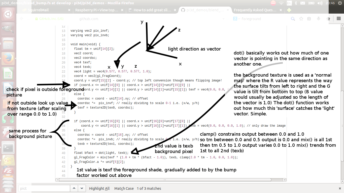
burn: compares the brightness of the background pixel with a sliding threshold to determine how much to mix the foreground and backgroundfalse: creates a false middle color using factors acting on the foreground and background RGB values and blends to and from the mid color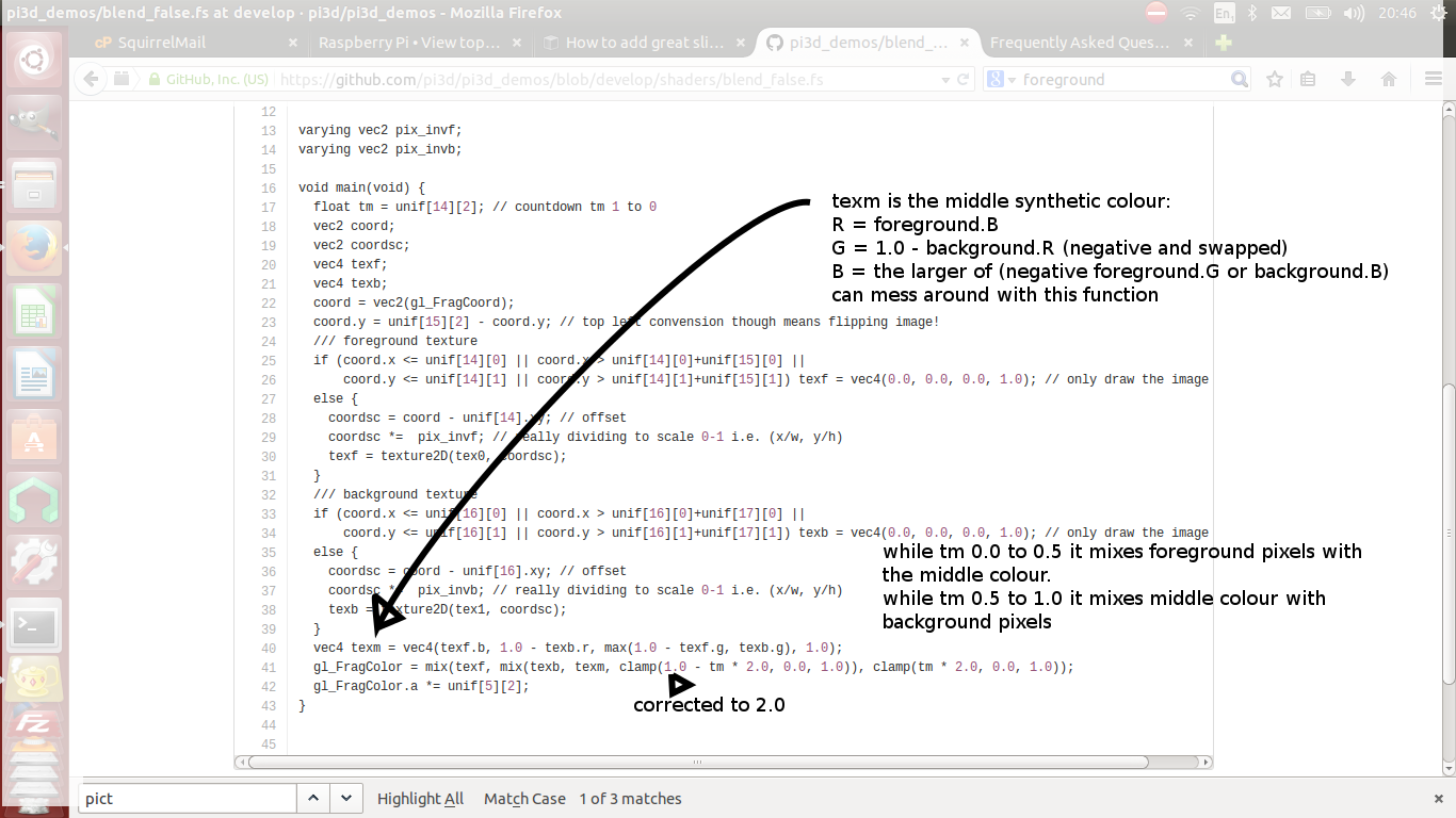
holes: uses the distance from a grid of points to determine the proportion of mixingstar: calculates the pixel position in polar coordinates (angle and radius) then does some trig to determine the blend proportion
I am trying to get the PictureFrame demo to work but get some errors and certain images don’t show.
The EXIF reader functionality in Pillow didn’t work properly in the version bundled with raspbian buster. Try upgrading it with:
$ pip3 install Pillow --upgrade --user
DIY Shaders
I want to try out a shader that I found on Shader-toy or similar. Alternatively I had a working shader and it’s stopped working.
From v2.33 pi3d looks at the version of OpenGL or OpenGLES and modifies the shader to match the specification of GLSL. The shader code now in pi3d and pi3d_demos matches the specification for OpenGL2.1. That means that if the rendering is being done by GLES2.0 (as with the Raspberry Pi up to 3) the
precisionline andversionline will be changed. If it is GLES3.0 then, additionally, theattribute,varying,texture2Dandgl_FragColorwill be changed. To facilitate this both the vertex and fragment shader must have lines:version 120 //precision mediump floatand in addition the fragment shader must have the line, somewhere before
main()://fragcolorAlternatively if you put your shader code as arguments to pi3d.Shader() then it will be used verbatim without any search and replace.
Points
How can I render points like a star field or sparks from an explosion.
If you use the method set_point_size() on a Shape to a value other than 0.0 then the vertices of the Shape will be rendered as points. The size will actually vary with distance but will be the size you specified at 1 unit of distance from the camera.
pi3d.Points can be used to render points using the mat_flat shader or special shaders as used in the demo
pi3d_demos/SpriteMulti.py
Lines
How can I render lines such as graphs or axes or the ‘wireframe’ version of a Shape.
If you use Shape.set_line_width() then the the Buffer objects in the Shape will have their draw_method set to GL_LINE_STRIP which will join all the vertices as point on a line. There is an optional argument
closedthat defaults to False which can be used to join the last vertex back to the first (by setting draw_method to GL_LINE_LOOP). To create your own lines you would need to make a list of (x,y,z) vertices and an element array to join them together and pass them to the Buffer constructor. The pi3d.Lines class does this for you.It is possible to create multiple Buffers within a Shape and set some as faces (draw_method set to GL_TRIANGLES) and some as points or lines. You can set different Shaders for different Buffers from v2.6
Using numpy arrays for Textures
I would like to do fast array processing with numpy and use the results directly as Textures in pi3d. How do I do this?
You can pass either a PIL Image or a numpy array directly to the Texture class as it creates an instance. The numpy array will need to have shape (H, W, N) where N is 4, 3 or 1 and the array must be
dtype=np.uint8If you attempt to use a slice of another array the resultant texture will be scrambled unless you make an explicit copy i.e.:ar = np.array([[[2 * i, 2 * j - i, i + j] for i in range(128)] for j in range(128)], dtype=np.uint8) tex = pi3d.Texture(ar[:50,:100].copy()) # try without copy()To refresh the Texture with a constantly changing numpy array use the
Texture.update_ndarray()method. This can be passed the new array as an argument, alternatively and faster, the Texture.image ndarray can be modified in situ and update_ndarray() called without any arguments.
Assigning different Textures to vertex groups
I want an ElevationMap with more detailed textures mapped to different areas. i.e. rock, grass, heather, swamp.
From v2.19 there are ready made shaders included to do this as well as an argument to specify how up to four different diffuse textures along with four different normal maps can be allocated on a vertex by vertex basis - seepi3d_demos/TigerTank.py.
Without PIL (Pillow)
Can I use pi3d without installing PIL - for instance trying to run on a different platform or to have an ultra small SD image?
Yes as of v2.15 you can do this but some of the classes will not work i.e. FixedString, Font, Building
The Pngfont will still work for rendering text. HOWEVER normal image files cannot be imported (jpg, png, gif) instead you have to convert these into compressed saved numpy files (npz) including any png files used as fonts. This can be done using a simple script on a machine that does have PIL installed:
from PIL import Image
import numpy as np
import os
dirctry = 'textures'
for f in os.listdir(dirctry):
  f = f.split('.')
  if f[-1].lower() in ['jpg','png','gif']:
    print(f)
    im = np.array(Image.open('{}/{}.{}'.format(dirctry, f[0], f[1])))
    np.savez_compressed('{}/{}'.format(dirctry, f[0]), im)
Minimal SD card
How can I set up an SD card without all of Raspbian’s clutter that will boot quickly and allow me to run a dedicated pi3d application.
This is what I did to get a version of the PictureFrame demo running on a Raspberry Pi that I wanted to just do this job without the need for Wolfram, Scratch or even the X11 desktop system.
1. The Raspberry Pi Foundation hosts a ‘stripped down’ version of Raspbian Jessie LITE avaliable at https://www.raspberrypi.org/downloads/raspbian/ which can be downloaded and burned to SD following the instructions there.
2. Start the Raspberry Pi logging in as user pi, password raspberry then:
$ sudo raspi-config
- boot options: console login as pi automatically
- internationalisation options: select relevant city
- expand file system
- (optional) change user password
- advanced: increase graphics memory to 128
- advanced: enable SSL
3. Install just the software to run the application:
$ sudo apt-get update
$ sudo apt-get upgrade
$ sudo apt-get install python3
$ sudo apt-get install python3-numpy
$ sudo apt-get install python3-pillow
$ sudo apt-get install python3-pip
$ pip install pi3d
4. Download the modified project from github:
$ wget https://github.com/paddywwoof/pi3d_pictureframe/archive/master.zip
$ unzip master.zip
$ rm master.zip
$ mv pi3d_pictureframe-master pi3d_pictureframe
$ cd pi3d_pictureframe
5. Checkout the excellent documentation by Tathros on which I have based these instructions. The main differences are getting it to work in console mode, without the need for a desktop environment:
### screen application needed to show output run from crontab ######
$ sudo apt-get install screen

### turn off screensaver ###########################################
$ sudo nano /etc/kbd/config
... BLANK_TIME=0
...
... POWERDOWN_TIME=0
CtrlX,Y,Rtn

### set up wifi (you will need dongle if RPi < 3) ##################
$ sudo nano /etc/wpa_supplicant/wpa_supplicant.conf
... ctrl_interface=DIR=/var/run/wpa_supplicant GROUP=netdev
... update_config=1
...
... network={
...         ssid="YOUR_SSID"
...         psk="YOUR_PASSWORD"
... }
CtrlX,Y,Rtn

### auto start and stop - only do after checking everything works ##
$ crontab -e
... # turn off screen at 21:00
... 00 21 * * * touch /home/pi/pi3d_pictureframe/stop; /opt/vc/bin/tvservice -o
... # turn on screen 07:00
... 00 07 * * * /opt/vc/bin/tvservice -p; /bin/chvt 2; /bin/chvt 1; screen -dmS PICFRAME /usr/bin/python3 /home/pi/pi3d_pictureframe/PictureFrame.py
... # kill any extra python processes that might have crept in
... 00 04 * * * killall python3
... # switch on at start up
... @reboot screen -dmS PICFRAME /usr/bin/python3 /home/pi/pi3d_pictureframe/PictureFrame.py
CtrlX,Y,Rtn
In these instructions the “…” at the start of lines represents the fact this is text inside a file and shouldn’t be actually typed in! Also you need to change the WiFi credentials to match your router, NB the SSID and PASSWORD need to be inside quotes. In the picture_getter.py script you will need to put in the email server, user and password for picking up images.
pypy
Does pi3d work with pypy
pi3d relies on some of the functionality and speed of numpy and this only really became usable as of pypy-2.2 and the recent versions of pypy-numpy need more recent versions of pypy (>4.0.1 or 4.4 see below and bitbucket.org/pypy/numpy)
As at 2017-04-24 I have installed and tested pypy on a Raspberry Pi 3 and on my ThinkPad i5-2410Mx4core laptop running ubuntu. It pretty much all works though there are a couple of features of numpy that still don’t. Fixes to Font and FixedString will be in pi3d from v.20 (in the develop branch from now). NB it’s generally a good idea to do all this inside virtualenv if you are thinking of using normal python at the same time
On the Laptop thefollowing steps seemed to get pypy working:
1. in a terminal install pypy from ubuntu:
sudo apt-get install pypy
sudo apt-get install pypy-dev
sudo apt-get install pypy-pkg-resources
sudo apt-get install pypy-setuptools # needed for Pillow install from source
2. download and install pypy-numpy I did this then changed to that directory:
git clone https://bitbucket.org/pypy/numpy.git --depth 5
cd numpy
sudo pypy setup.py install
# you can then delete this directory
3. download Pillow source from https://pypi.python.org/pypi/Pillow and extract it, cd to that directory and install as above:
cd Pillow-4.x.x
sudo pypy setup.py install
# you can then delete this directory
On Raspberry Pi raspbian stretch (Aug 2017) pypy v5.6.0 is already installed however, for some reason, pypy pip has not been, which limits use to core or pure python modules. Also I found that neither the latest version of numpy or pillow worked:
1. Get hold of pip for pypy:
cd ~
sudo curl -O https://bootstrap.pypa.io/get-pip.py
sudo pypy get-pip.py
pypy -mpip install -U wheel
2. Pip install numpy NB using pypy -mpip ..:
pypy -mpip install cython
sudo apt-get install pypy-dev
sudo pypy -mpip install numpy==1.12.1
3. Pip install PIL agian pypy -mpip ..:
sudo apt-get install libjpeg-dev #zlib1g-dev libpng12-dev libfreetype6-dev # seemed to cause errors
sudo pypy -mpip install Pillow==4.0.0
Prior to stretch (i.e. jessie) I found that the pypy installed is v4.0 and pypy-numpy demands > v4.4 so this is what I did (NB I noticed subsequently that there is an option to install numpypy for pypy4.0.1 - see the bitbucket/pypy/numpy page if you want to try this first):
1. download and unzip the latest stable release of pypy for raspbian. As at now
https://bitbucket.org/pypy/pypy/downloads/pypy2-v5.7.1-linux-armhf-raspbian.tar.bz2I put this as/home/pi/pypy2-v5.7.1-linux-armhf-raspbian/2. to save confusion I overwrote the symlink to the previously installed pypy-4.0. In a terminal:
sudo ln -s -f /home/pi/pypy2-v5.7.1-linux-armhf-raspbian/pypy /usr/bin/pypy3. I tried the three apt-get install instructions as per ubuntu but only pypy-dev seemed to work. It wasn’t clear how to use pip with pypy but in the end I did the following in a terminal:
cd /home/pi/pypy2-v5.7.1-linux-armhf-raspbian/
pypy -m ensurepip
bin/pip install -U pip wheel
bin/pip install pkg_resources
I think there was an error but
import pkg_resourcesseemed to work after this.4. At one stage I installed all of the following, many may not be needed but some might. You could try without first I suppose, but it didn’t take too long.:
sudo apt-get install gcc make libffi-dev pkg-config libz-dev libbz2-dev \
libsqlite3-dev libncurses-dev libexpat1-dev libssl-dev libgdbm-dev tk-dev \
libgc-dev python-cffi liblzma-dev
5. For Pillow to work you need these (that’s a ‘one’ in zlib1g-dev by the way):
sudo apt-get install libjpeg-dev zlib1g-dev libpng12-dev libfreetype6-dev6. Download, extract and install pypy-numpy. I used git, as with ubuntu above.:
git clone https://bitbucket.org/pypy/numpy.git --depth 5
cd numpy
sudo pypy setup.py install
# you can then delete this directory
7. Pip install Pillow:
cd /home/pi/pypy2-v5.7.1-linux-armhf-raspbian/
bin/pip install Pillow
For both these installations you will need to pip install pi3d (using the pypy pip) or download (or git clone) pi3d and use
sys.path.insert(1, '/home/pi/pi3d')beforeimport pi3d. The pi3d_demo files do this automatically.At the moment the PexParticles and Pong demos fail mainly due to non-implemented features of numpy (einsum, interp, remainder and outer). The speed benefit of running pypy won’t improve the GPU functionality or the numpy calculations but in some areas where there is a lot of looping in the python code there could be gains (
pi3d_demos/CollisionBalls.pyfor instance).
DIY environments
Cube
How can I make my own EnvironmentCube images using pictures of my garden or school playground?
Option 1. Using an EnvironmentCube (as the question says) but see below for using a Sphere, which is probably easier.
There are lots of ways of doing this and different software as well as special cameras. However this is the method I have followed using freely available software: gimp and blender (running on a ‘normal’ computer rather than the pi at this stage).
The first half of the job is to get a set of images into a ‘seamless’ band. Obviously you need to have taken a set of pictures that overlap 25% to 50%. In gimp make a new image that is higher and wider than you will need to paste all the images side by side. You will need to have the same image repeated at the left end and the right end.
Open each image in gimp then copy it, go to the new ‘wide strip’ image and paste as new layer. Use the four headed arrow to position each layer so it ‘joins up’. When you put the duplicate left most image at the right end you need to make sure that it is at exactly the same vertical position as it is on the left.
Working down from the top layer add layer masks (default white, full opacity) then using gradient fill tool make the mask fade from transparent to opaque across the overlapping portion. You might need to slightly rotate some images to make them join up nicely from one side to the other.
When it looks perfect (!) merge the layers down then crop the image so there are no gaps at the top and bottom and so the left and right edges join seamlessly. You will probably have to zoom to maximum and choose an easily identifiable pixel. The rectangular selection tool in gimp allows the edges to be dragged to fine tune it. Export the image to jpg or png possibly after reducing to a reasonable size. Have some suitable sky only image to patch into the top of the sphere you will create in blender…
I used blender 2.69, it’s not a trivial application if you’ve not used it before and it might take a bit of effort to figure out what I’m referring to [tab] means tab key, otherwise it’s probably a menu item or an icon in the right hand. Lots of youtube videos to look at. In blender:
1. [del] delete the startup cube
2.
Add Mesh UV Sphere, on left tools setShading Smooth3. [s] to scale up to about 10x
4. [tab] to edit mode [a] to deselect all vertices. R-click on top vertex the Ctrl-numpad+ to select vertices down to about 45 degrees north (or use [b] and box select) [del] delete vertices. You should now have a sphere with the top cut off
5. [tab] back to object mode then create another sphere at the same location but scale it up very slightly bigger and chop off the bottom but so they overlap just a little.
6. [tab] back to object mode then
Add Empty Cubeat the same location (NB if you accidentally left click on the view window you will move the starting point marker where new things appear). You should be able to zoom in with the mouse wheel and see this cube inside the spheres.7. still in object mode right click to select the bottom (inner and larger) sphere. The edge should go yellow to indicate it’s been selected.
8. on the right properties window click the Materials icon (CofG circle 4th from right), then + new.
9. then click the Textures icon (red/white check 3rd from right), then + new,
Type Image or movie,Image Newbrowse to the wide horizon image you made,Mapping Projection Tube10. still in object mode right click on the top sphere, add material and texture exactly as for the bottom sphere but select the patch of sky image mentioned above and choose
Mapping Projection Flat11. in object mode right click on the Empty Cube and add a new Texture (you should see a reduced list of options so it’s 2nd from right in the list)
12. select under
Type Environment Mapthen underEnvironment Map Static,Mapping CubeandViewpoint Object Empty13. in the properties icons select render (camera left most) then under Render press the render button. This should flash up a series of six smaller images then go black!
14. re-select the Texture icon (all of these steps should have the Empty Cube as the selected object) and the little down arrow under Environment Map should produce a drop-down menu with an option to save the image.
The texture can then be used in pi3d with EnvironmentMap type BLENDER. However there will be a sharp line where the edge of the bottom sphere fell. You can smooth this out using clone, repair, blur and blend tools in gimp; be careful not to blur the boundaries between the six images.
Sphere
How do I make an Environment Sphere (such as can use the Photo Sphere images created by later versions of Android)
First you need an image very much like the one outlined in the previous question. If you have the software on your phone or tablet to do a Photo Sphere that’s going to be a lot easier but you can do something similar with a series of panoramas as modern cameras can make. The image needs to be twice as wide as it is high using a standard cylindrical projection http://en.wikipedia.org/wiki/Equirectangular_projection
This image is used for a Texture uv mapped to a standard pi3d.Sphere but the Texture needs to have the argument
flip=Trueand the Sphere needs the argumentinvert=TrueIf the same image is used as the reflection with
uv_reflectormat_reflectshaders then the correct part of the scenery will be rendered - i.e. behind the camera and transposed left-right, see demopi3d_demos/EnvironmentSphere.py.
pickling
How can I speed up loading Models. Even quite low polygon counts seem to take ages on the Raspberry Pi
Thanks to Avishay https://github.com/avishorp it is possible to use the python pickle functionality to serialise pi3d Shapes including Model.
There is an example on github.com/pi3d/pi3d_demos
pi3d_demos/LoadModelPickle.pywhich shows the process but basically:load the models once normally, create a file (has to be binary for python3) to write to, then
pickle.dump(mymodel, f)subsequently open the file to read from and
mymodel = pickle.read(f)the loaded file will have any required Textures included automatically including bump and reflection maps. However the shader will still need to be set withset_shader()Loading from a pickle file is significantly faster than parsing a wavefront obj file but (because of the less efficient image compression) the disk space used will be much higher.
Strings
quick change
How to have lots of rapidly changing text on the screen (such as location game-status readouts etc) whithout having to create new String objects all the time (with associated processor load)
This can be done using the String.quick_change() method.
When you first create the string you need to make it big enough to fit in any additional characters you may send to quick_change() subsequently. At the moment it doesn’t cope with multi-line Strings.
There is an example in
pi3d_demos/ForestQuickNumbers.py
Why do I get an error when I try call the quick_change() method in my program.
If you getAttributeError: 'Buffer' object has no attribute 'vbuf'then this could be because you are calling quick_change() before the first draw() of the String object. Unfortunately you can’t do this (as at pi3d v2.10) and you will have to alter your code to ensure the draw happens before the change.
FixedString
How to have a large amount of text without creating hundreds of extra polygons for the gpu to render?
The String object has a little rectangle for each letter, each of which needs four vertices and two triangles. If the text does not need to be changed then it is better to use the FixedString class. The object inherits from Texture with the provided text drawn onto it. It also creates a simple sprite with four vertices and two triangles that can be used to draw the texture. There are filters that can produce effects such as blurring, outlining and normal map generation.
PointText
I want lots of text changing in real-time, scrolling, rotating, fading or changing colour.
For complicated things like this then the PointText class should be used (with TextBlock components) seepi3d_demo/StringMulti.py
Shadow
How can I make my text show up against different coloured backgrounds (such as when displaying the score as 2D text)
There are two ways to do this in pi3d. The first is to define a background_color in the Font or FixedString with a low alpha value (say 20 out of 255). This will produce partially transparrent background for your letters which will be a rectangle if you are using a FixedString but will be uneven edged if you are using a normal String with Font. If you set the alpha to zero you will end up with a subtle line around the outside of each letter, which may be enough. (See also below for dealing with uneven edges)
To get a larger outline around letters you can specify a shadow_radius and a shadow RGBA value (default black with no transparrency). This produces a gaussian blurred version ‘underneath’ each letter. See the Shapes demo for how this might look.
Sharpen Large characters
How can I draw large characters on the screen without getting a grainy ‘enlarged image’ effect.
When the font is created the default is to use a grid of 16x16 on a 1024 pixel Texture. Also, to allow rotation the characters are shrunk withing the 64 pixels that allows. From v2.29, If a smaller character set will suffice then a different grid_size argument can be used and subset defined with the codepoints argument. See the Slideshow_2d.py demo
Normal Map generation
I have a low polygon model that I want to appear more detailed. I know I
can do that if I have a normal map to supply to the .._bump or .._reflect
shaders. Is there a way to generate these automatically.
Yes. If you simply use the same image file for the texture and the normal map then this will alter the lighting of the surface. However this will often give rather strange effects due to the interpretation of surface normals from RGB values. To get a better result you can create a version that uses the lightness of the image as a height map, for instance in
pi3d_demos/Water.py:shapeimg = pi3d.Texture("textures/straw1.jpg") shapebump = pi3d.Texture("textures/straw1.jpg", normal_map=-6.0)The size and sign of the normal_map argument can be used to compensate for the contrast and positive/negative nature of the image.
Alternatively you can make a copy of the colour texture image and edit it with GIMP (or similar) to make a greyscale version that matches the surface geometry you want.
Texture animation
Is it possible to change a texture every frame at a reasonable frame rate? i.e. for displaying a video, a feed from a web cam or an image manipulation program such as OpenCV, Scipy or numpy?
This became much more feasible after v1.4 and more so after v2.1 The Texture class now accepts a numpy array (size (H,W,N) where N is 3 for RGB or 4 for RGBA), remember C arrays are row,col,pixel)
There is also a method Texture.update_ndarray(new_array) that can efficiently switch the image to the new array. See the demo
pi3d_demos/VideoWalk.pywhich maps a movie onto a shape using ffmpeg.A much faster system can be used on the Raspberry Pi that utilises the C code used in the demos in /opt/vc/src/hello_pi. This is tricky programming but a working version has been created by @swhner https://github.com/swehner/foos/blob/opengl_replay/foos/ui/opengl_replay.py and https://github.com/swehner/foos/blob/opengl_replay/egl_replay/video_helper.c
Profiling
How to profile code to find where the bottlenecks are? For example to find if it’s worth doing something complicated with numpy or ‘blitting’ small areas of the screen as in the NumpyBalls demo?
The python profiler cProfile is very easy to use but I have found it struggles to find directories from the code and gives quirky information unless I do something like:
$ cd ~/pi3d_demos
$ python -m cProfile ~/pi3d_demos/NumpyBalls.py > result.txt
Desktop or laptop
Is it possible to use pi3d on my laptop or desktop computer ideally running windows?
If your computer has a suitable graphics card then you should be able to do this.
Raspbian Pixel is probably the easiest to set up from scratch and most closely matches behaviour on the Raspberry Pi, if you are happy booting onto a USB stick see ReadMe Linux
windows requires a version of pi3d v2.0 or later see ReadMe Windows
linux is more similar to the Raspberry Pi, also see ReadMe Linux
mac ought to be possible following a very similar procedure to linux but I havn’t tried (let me know if you do!)
On windows or mac it is also possible to use something like VMWare:
Setup:

VMWare Client
3d Accel.. activated!
LinuxMint Installation (Ubundu-based and Debian base version works)

very important
    mesa-utils-extra
    python-numpy
and the rest as described in the Pi3D documentation

Important: pi3d scripts must be started with sudo

e.g. sudo python ./Pi3D2.py

In the VM it does not run very smooth, but it works without errors.

After testing this setup  I've installed the setup to a partition... runs like a charm :-)
comments by @hesspet in groups.google.com
Android
Is is possible to run pi3d on my Android phone or tablet which uses a chip and operating system very similar to the Raspberry Pi?
Is is possible; but you have to compile an apk package using python-for-android from a linux machine. There are instructions here http://pi3d.github.io/html/AndroidUse.html
Targetting
Identify what’s in front of the Camera
How to find the name of the object in the camera’s target (pi3D 3d world) example:https://www.youtube.com/watch?v=0u91pcNXtcI&feature=autoshare sun, world, astroid123?
One approach would be to look at the size of the angle between the direction to each possible target and the direction the camera is pointing. You would then choose objects where that angle was smaller than a threshold then choose the nearest if more than one. Say in
pi3d_demos.ForestWalk.pyyou had kept a dict of different objects as obj_dict, you could add a print() when you press the ‘h’ key:obj_dict = {'monument':monument, 'trees1':mytrees1, 'trees2':mytrees2, 'trees3':mytrees3} THRESHOLD = 0.95 ... elif k == ord('h'): nearest = None target_name = None for o_name in obj_dict: o = obj_dict[o_name] v1 = o.unif[0:3] - CAMERA.eye # numpy vector from camera to object dist = (v1 ** 2).sum() ** 0.5 v1 /= dist # divide by length v2 = CAMERA.get_direction() # already length = 1 cos_angle = v1.dot(v2) # 1 straigt at it, 0 at right angles, -1 opposite direction if cos_angle >= THRESHOLD: if nearest is None or dist < nearest: nearest = dist target_name = o_name print('nothing' if target_name is None else target_name)However this only works for smallish objects. If you want to see if the cross-hairs are hitting the Earth on the meteorize game then you would either have to include a size factor into the obj_dict above instead of using an overall threshold i.e.:
obj_dict = {'monument':[monument, 4],
    'trees1':[mytrees1,15],
    'trees2':[mytrees2,20],
    'trees3':[mytrees3, 20]}
o = obj_dict[o_name][0]
sz = obj_dict[o_name][1]
if cos_angle > (1 - (sz / dist) ** 2) ** 0.5
Though this method would have issues with large objects such as the merged ‘tree’ objects in ForestWalk, where it is possible to be ‘inside’ the object.
Or look at each face of the object and see if the vector intercepts each triangle - but this would be very slow. See the Pong demo and the ElevationMap.clashTest() method.
Finally a fairly efficient but technical method would be a variation of the Clashtest system using glScissor to draw a single pixel of each object to an offscreen texture with different RGB values for each then checking what if any had been drawn.
Bullets
How to create bullets and shoot targets? (like counter strike)
The bullets in Counter Strike just look like streaks of light with some smoke so the best way is probably something like the bullets in DogFight. This uses two Plane objects merged at 90 degrees to each other with a series of images that can be mapped onto them in sequence (there are two sets of guns on the Aeroplane which is why there are four Planes).
In the
pi3d_demos/TigerTank.py(from v2.23) there are missiles (purple beer bottles) and you can aim (mouse rotates, u, j raise lower gun) and fire (f)How you animate the target being shot depends on the effect you want. In the meteorize game I use a part transparent texture and scale the meteors up so they look to be bursting soap bubbles.
Laser sight
How to create a laser point for gun?
This is the kind of thing you can do. For example to modify
pi3d_demos/ForestWalk.pyto include a laser dot:1.Copy the shaders you want to get lasers on to the pi3d_demos/shaders directory and rename i.e. uv_bump_laserdot.vs, uv_bump_laserdot.fs
2.edit the fragment shaders i.e. uv_bump_laserdot.fs and add the two lines:
#include std_bump.inc
  float radial = distance(vec2(gl_FragCoord), unif[15].xy); // 1 --- distance from centre of screen
  texc.rgb += vec3(5.0, -2.0, -2.0) / (dist * radial); // 2 --- increase R, decrease GB reduce size in distance
  gl_FragColor =  (1.0 - ffact) * texc + ffact * vec4(unif[4], unif[5][1]); // ------ combine using factors
2.change ForestWalk.py to use the new shaders:
# load shader
shader = pi3d.Shader("shaders/uv_bump_laserdot")
...
3.change ForestWalk.py to add the x, y location of the screen midpoint to each Shape that uses the new shaders:
...
mymap.set_fog(*FOG)
mymap.unif[45:47] = [DISPLAY.width / 2.0, DISPLAY.height / 2.0] #or use mymap.set_2d_size(DISPLAY.width / 2.0, DISPLAY.height / 2.0)
You could take an alternative route if you are using the obj_dict idea from above. In that case you could simply draw the laser dot in the middle of the screen (i.e. using a Camera(is_3d=False..)) and scale the dot according to distance to the target. The disadvantage is that the dot wouldn’t scale correctly on very large objects such as the terrain.